The folks at Xiegu have released a new firmware update for the x6100 HF transceiver.
From the changelog:
New firmware version information is as follow after upgrade:
APP  : V1.1.5 Apr 10 2022,13:12:01
BASE : V1.1.5 Apr  9 2022,17:14:40

For all the previous fw download, visit < www.radioddity.com/x6100-firmware >
-------------------------------------------------------------------

2022.04.18 Upgrade Log
Main file: sdcard.img
SHA256: C6CDE4E7546842C7693D2A20B193D18017F2C17C4F644D56A36218CD22836B41

App: V1.1.5 Apr 10 2022,13:12:01
1. Fix bug: the last character in the string of "AGC mode" is half cut off in MEMO mode
2. Fix bug: CW decoder not working
3. Fix bug: incorrect UTC offset/Time zone
4. Change the range of built-in/handheld speaker's MIC gain:
   Old version:  range 0~36, default 10; actual gain 0~+18dB, step 0.5dB
   This version: range 0~50, default 20; actual gain -10~+15dB, step 0.5dB

Base: V1.1.5 Apr  9 2022,17:14:40
1. Fix bug: battery can't be fully charged
2. Fix bug: won't charge at power off state (occasionally)
3. Fix bug: have to switch band or press PTT once at the first time of power up, or there's no output RF power
4. Fix the problem that the built-in/handheld speaker's MIC gain is too high
5. Fixed the problem that the gain adjustment of the built-in/handheld speaker is not obvious
Please do note that upgrades are a two-step process – upgrade of the system software and upgrade of the baseband. The second step will fail if you are not plugged into external power.
WARNING – Image-heavy post ahead. You might regret it on mobile 😉
A while back I sold my Yaesu FT-817ND.
Yes – I make mistakes.
Recently I saw a listing for a FT-817 that included an Elecraft T1 Automatic Antenna Tuner for a price that I couldn’t say no to (think less than the price of a used FT-817 itself), so I took the chance and I am now the proud owner (again) of this wonderful little rig.
Fortunately both seem to be in good working order, so I am grateful to the seller for offering up this package as I had also been eyeing the T1 for the last few months.
The FT-817 is not the most power efficient portable rig out there, but it is so common that there are a number of accessories and mods that can be done to extend the usefulness of it well beyond its age.
It is sturdy, well built, and gives full coverage for HF/6M/2M/70CM bands. Not many rigs out there can say the same.
But……
My old one had the Yaesu YF-122c mechanical filter installed.
My new one does not.
Finding a new or used YF-122c (note the “c” – the “s” model is widely available) is like finding that ultra rare DX with no pile-up – it doesn’t happen every day and conditions don’t always make the QSO happen.
My search for a filter module ended in vain…or did it?
"The LASERBEAM-817 Filter Module has been designed specifically for the FT-817. It provides two high quality audio filters (SSB and CW). These audio filters can be used with the optional filters in the FT-817 to greatly improve their performance or as a cost-effective alternative to installing a plug-in CW filter."
Additionally, it provides two filters in a single package: a SSB filter that covers 300-2700Hz and a 500Hz (450-950Hz) CW filter.
Switching between the two is supposed to be automatic.
To me that brings two main advantages; it covers both SSB and CW filtering, and it can be used both with and without the optional YF-122x filters.
Obviously in my case it is the without that is most appealing.
Oh, and it costs roughly 75% less than what I have seen the SSB mechanical filters alone going for online.
The LASERBEAM-817 Filter Module is not “plug and play” – it requires the installation of new capacitors (if you don’t have a mechanical filter installed as well), soldering of wiring to the Main PCB, mounting of the module inside the case, the removal of a SMD capacitor, and the moving of the built-in speaker to make room for the filter module.
But, as they say in the manual, “The installation requires modifications to the FT-817. These should be within the capability of anytechnically competent radio amateur“ (my emphasis added)
Whelp…time to see if I am competent or not.
Disassembly of the Radio
The instructions are well written and clear, but online there is very little information about both the filter and the installation of it. Sotabeams actually refers to some external services who will perform the installation for buyers, but again it should be within the skillsets of most hams.
I’m hoping that documenting the process I did for install might help someone else who is looking for a CW/SSB filter for their FT-817.
NOTE: This is a modification of your radio. It requires you to do soldering of new wires, components, et al to the internals of your radio. There is in all likelihood no warranty coverage by anyone if you mess things up. Mistakes may mean a bricked or broken radio.
Also, any images I have provided below must be double and triple checked against their instructions AND schematics to ensure that they are correct. I make no promises that this is exact and without fault – it is just what I performed and worked for me.
Please do the right thing and validate EVERY step of the process yourself – do not rely on my words or images.
Proceed at your own risk.
I highly recommend – as with any project – taking photos with your phone as you go. It helps me to remember exactly how things should be put back together.
The first thing was to remove the top cover.
As with anything electronic, proper precautions should be taken to avoid any static discharge potential, and you should carefully inventory every screw, connection, part, etc. to make sure that when you’re done putting things back together, that there are no “extra” parts laying around.
😉
Then you need to first remove the 5 screws that are holding the PCB in place, and then carefully disconnect the small ribbon cable as noted in the image below. (Red Stars = Screws | Purple Star = Ribbon Cable)
After doing that, you need to unplug the two coax connectors (red stars). Don’t forget which one goes where.
Finally, carefully flip the PCB over the front of the radio. Note that the battery cable needs attention as you do so in order to avoid snagging it and having bad things happen.
I chose to use an empty solder spool as a support for the PCB to avoid any unnecessary strain on the remaining ribbon cable.
Installation – Prep Work
Now is where things get real.
Because I do not have the aforementioned YF-122c mechanical filter, I have to install two capacitors on the PCB.
The first one is from the input of the ceramic filter to the optional filter.
The second one is from the output of the ceramic filter to the output of the optional filter.
They include some tubing to use for insulating the contacts to avoid shorts. I chose to loosely cover the capacitors end to end in my own. Note that in this photo the yellow wire is attached – more details on that below.
Now it is time to route power from the top of the board around to the bottom where we’re working. This is well documented with both text and images in the supplied documentation, but I’m showing my outcomes here for your reference.
This is done by soldering supplied red wire to the emitter of Q1082.
And then by soldering the black wire to a ground point.
Then a yellow switching wire is soldered to the collector of Q1083 (red star below and shown in an earlier photo). This is a really small connection so take your time and use a lot of care. There is what looks like a SMD resistor right next to it – a very fine tip on your soldering iron is needed here. That and a magnifying glass (for me at least).
Now we’re going to take a break from adding new things to the PCB and actually remove something.
C1338 is a SMD capacitor that needs to be removed so that we can use the connection points to add more wiring. They recommend quickly alternating with a soldering iron between the two solder points until it can be easily removed.
I have a soldering/desoldering station, so I used that to heat up the contacts until the capacitor would easily slide off and removed it. It is now safely taped to the underside of the top cover so that I can reverse this modification if desired.
We need to take two screened wires and solder the red and white cores to the upper and lower capacitor pads. Because the cap we removed is SMD, the pads are extremely small. Use a fine tip on your iron and move slowly.
The screens of both should then be tinned and and soldered together to ground. Unlike the red and white wires above, the ground you’re soldering too is quite large, so switching to a larger tip on your iron might help get a better connection more quickly.
Now we’re done with the bottom of the PCB. We can carefully turn it back over – watching to make sure any wiring is routed correctly – and we can do some initial checks.
Note that the wires we’ve connected to the bottom of the PCB must be routed around to the front and to the same spot where we’re going to mount the filter module.
Follow the well documented steps in the manual and you’ll get it right.
The documentation states that we should be able to apply power to the radio and verify that we can measure the power via the new red and black wires.
Additionally we can toggle the filter in the menu and validate that the yellow wire voltage toggles between 0.4 and 6.5 volts for narrow and wide respectively.
DISCONNECT THE POWER BEFORE PROCEEDING
Installation – The Module
Now we’re going to wire up the module itself to the new connections that we’ve prepared.
The red and black wires will be soldered directly to the module. Note that you should not solder through the holes as we want the module bottom to be flat for mounting.
The yellow wire needs to be soldered to two resistors, which then are soldered across two pads. Twist and solder the two resistors together, creating a “T” shape where the connection is the vertical part of the “T”, and the two resistors and wires form the horizontal portion.
Yellow wire needs soldering as does the red and white wires, but the two resistors and red and black wires are all in place
Solder the junction of the two resistors (the vertical section) to J1 pin 8 (screened as RA2 on the PCB).
Solder the one end to ground which is pin 1 on J1.
Solder the free end to the yellow wire.
Now we’re going to solder the screened wires to the module.
I had a little confusion at this step. The documentation states to “Dress the end of the screened cable. Solder the screens together – but not to anything else.”
It took me a couple of reads to realize that dressing the end of the screened cable means to trim them short enough to not cause any shorts with the other connections, as they are not going to be soldered anywhere.
I’m slow.
The white core will then be soldered to J1 pin 7 (AF IN), and the red core to J1 pin 6 (RB15).
Power up the radio again and toggle between wide and narrow in the settings. The PCB has an LED that will be lit when WIDE is selected, and off when NAR is selected.
The instructions state that we should be using the supplied adhesive tape to mount the module to the PCB before testing, but also notes that it might be easier to do so prior to soldering the connections.
NOTE: I repeatedly went through the shipping envelope and pouches looking for that adhesive tape.
It is there – already on the bottom of the module. Doh.
Now to move the speaker.
The stock mount for the speaker does NOT mount it centered in the speaker grill.
The speaker needs to be moved to ensure that it does not sit on top of, and therefore press the button that is on the top of the filter module.
They recommend ensuring that it sits centered in the speaker grill, and making sure that it sits over the top of the processor on the filter module.
Mounting options abound including tape, hot glue, etc.
Noting that the screws used to secure it are inserted into threaded holes in the mounting bracket, I figured I would simply reposition the speaker and drill new mounting holes. That way I’m not relying on a connection that could come loose later on.
It does add another hole to the top of the case, but like my father always said “if you want to keep it new, leave it in the box”.
Except……that doesn’t work. The metal mounting bar will hit other components and not allow you to reattach the top cover.
So don’t be me – follow the directions (have I said that enough?).
I’ll just go back to my corner and contemplate my mistakes.
But my radio now has an extra hole in it.
More aerodynamic? Let’s more RF in for better reception?
Sigh.
Conclusion
Overall the module installation wasn’t bad. On a scale of 1-5, with 5 the most difficult, I’d put it at a 3.5 – 4. The documentation is well done and clearly written. There are several points that requires some precise soldering skills, something that someone with an unsteady hand might struggle with.
I do have some worry about a couple of the really small soldering connections, and may go back and apply some liquid electrical tape or something just to give a little strain relief. The SMD pads are tiny, and there isn’t much surface area to keep things from vibrating loose over time.
But….
Did it work???
YES!!!
With the filter installed, I can now enable it via menu option 39, and a significant difference in the audio quality can be heard on CW (my preferred mode) and slightly less significant difference on SSB (only done spot checks).
Here is a short audio recording of the filter in action on CW.
NOTE: This post is provided for informational purposes only and I do not promise nor do I guarantee that I have written instructions, or created images that are 100% accurate. Please use Sotabeams’ posted instructions if you choose to do this modification.
Alternative Approach (September 5, 2022)
You can see in the comments that I noted in one exchange about having gone a different route with my other Yaesu, the FT-818.
I had found one of the last Inrad built PCBs but used the same filter that he bought on eBay. So far, so good. Looks like another source for PCBs exists.
If you have solved for the elusive YF-122c filter in creative or similar ways, let me know in the comments.
I’ve had a couple of days to play with the new (tr)uSDX 5-band transceiver and I thought I would do a quick post to show my initial impressions of this kit.
Overview
The (tr)uSDX Radio is a project created by DL2MAN and PE1NNZ, based off of the uSDX project.
It covers 5 amateur bands – 80/60/40/30/20 meters and is multi-mode – CW, SSB (LSB|USB), and AM/FM.
There is an onboard speaker and a mic, though external ones are recommended.
Please keep in mind that this project’s intent was to (through the use of group buys, etc.) allow for a user to acquire the necessary parts for about $50 USD. With the supply chain issues affecting the whole world right now, sourcing parts is increasing that cost quite a bit, so authorized suppliers like those they’ve partnered with are one of the only reliable methods of getting everything in an easy fashion.
Please also keep in mind that this radio is not an IC-705 or a KX2. It is not meant to be, and my comments below will be framed within the context of what this radio is, not what it isn’t.
It’s Here!
Note that I ordered two – one pre-assembled with the case, and one that is the raw kit without the case (I’m 3D printing my own).
This gives me the opportunity to see if there are any advantages to either method other than price. That and I like radios.
It is an addiction.
It arrived safe and sound on Thursday, April 7th. My first impressions when receiving the box was:
“OH NO!”
Those fears were unfounded as the rig was well padded inside with very thick and sturdy bubble wrap.
Packaged in the box is the radio and an unterminated power cable.
The bubble wrap they used is not the standard type that is seen in packaging all over, rather it is of a series of long inflated tubes. The material is quite a bit stronger than typical bubble wrap and takes a lot more effort to puncture.
A+!!!
Part of building the (tr)uSDX is loading the boot loader, then using the serial number to download a personalized firmware image.
The supplier does all that for you, and provides a label on the packaging including the serial number for your reference when doing firmware upgrades.
If you lose it, the only way to see your serial number again is to re-flash the boot loader and erase the existing firmware.
So far so good.
Before getting anything powered up and on the air we needed a power cable. The supplied cable is a 3.5mm to 1.35mm DC plug. It is smaller than the standard 5.5mm to 2.1mm plugs that most radios accept, and so you will need to either attached some connects to the bare ends of the plug, or get an adapter.
I found an adapter on Amazon that lets me avoid using yet another set of Powerpoles and instead use the existing plugs I have to bring the size down to what this radio needs. You can grab a set at on Amazon at https://www.amazon.com/dp/B07FJLZGPF?th=1
Or you can attach a set of connectors of course.
The Radio
The supplied case is 3D Printed and feels like it is done out of PETG. The quality of the print is quite good – the details are all there, the seams are solid and it just feels sturdy. The orange feels like the same shade of orange sherbet ice cream – kind of washed out in color.
I think if I had to do it over again I might have chosen the other color which is an olive drab. I say that as a fan of the color orange.
Just nit-picking on my part.
The case design, is in my opinion, superb. Everything was well thought out. There are four individual side pieces, and a top and bottom piece. The sides have internal slots that the PCBs fit into, securing them in place.
There is absolutely no wiggle room in any part of the case. Everything is tight and snug.
The tuning knob is also 3D printed, and fits tightly onto the stem without worry about falling off. There is no set screw, nor is there one needed.
It is all held together by 8 flat headed screws.
The whole case (minus the knobs, screws, and BNC adapter) measures 60.5mm by 90mm by 30mm.
Or in other words, about 2/3s the length and width of my iPhone.
It is tiny.
They must have a dual nozzle printer, or at least one that is capable of pausing to change out filament colors as the raised lettering is black filament printed on the orange base. It isn’t painted.
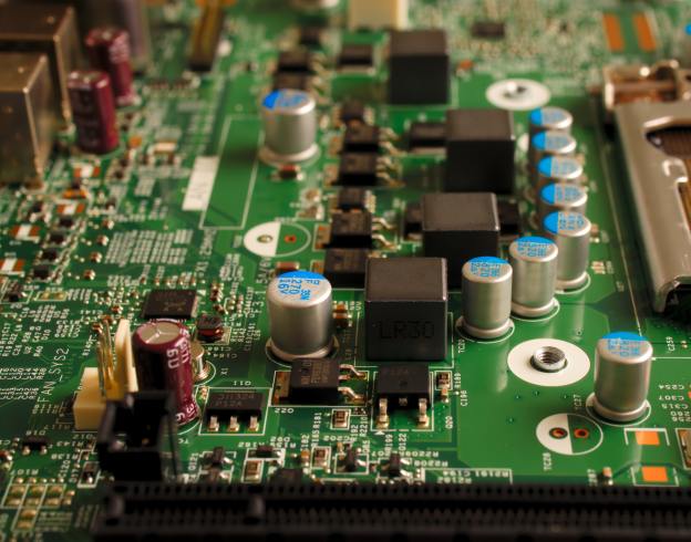
The power portUSB power and PAThe bottom of the rig – if you look closely you can see that the left side – in the middle – has a slightly darker rectangle. That is a thinner section that can be removed to allow direct access to the AVR programming pinsThe working end of the radio – Mic/Key port, Audio port, and the BNC to SMA connector (included) The RF board in all its glory! Note that all the windings are evenly spaced, and everything is neat and tidy.
Size Comparison with QCX-mini
Size-wise the two radios are extremely close, with the (tr)uSDX only slightly thicker front-to-back.
That makes the capabilities of this little transceiver even that more amazing to me – it is multi-band and multi-mode in a package that is similar to, what I think anyway, is the best portable single-band CW rig available.
There are tradeoffs for that though as we’ll see shortly. (again, not speaking to that as a negative, rather recognizing that this is a jack of all trades type radio and not a master of one, whereas the QCX-mini does one band and CW extremely well)
First Time Powering On
Upon powering up the radio, you are greeted with your callsign on a brightly lit interface. The onboard speaker is quite small, and results in a ringing tone when driven by too high of volume as to be expected given the size.
It automatically shuts off when an audio cable is inserted for an external speaker or headphones.
There are four buttons – Menu, Enter, PTT, and the tuning knob can be depressed for certain menu navigations, and the speaker rounds out the front face of the case.
There are built-in calibration tools, including a meter that shows power output and relative efficiency.
Out of the box I got the following:
Band
Power Output
Efficiency
80 meter
7.88 Watts
76.62%
60 meter
6.54 Watts
89.86%
40 meter
6.87 Watts
89.48%
30 meter
7.78 Watts
88.18%
20 Meter
7.06 Watts
86.87%
I’m comparing that to what others are seeing and, after watching DL2MAN’s calibration video, I may tweak things just a bit.
Not too much though – its pretty good out of the box.
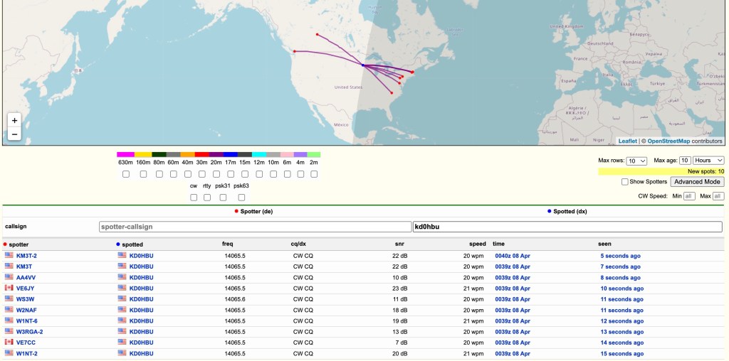
Next step was to get this on the air and see what RBN could see.
I hooked it up to my 20m Dipole which is suspended about 39-40 feet up in a tree.
Ok – so we know it gets out there 😉
I did call CQ a few times and even tried hunting a POTA activator or two, but given the time of day and the low power, I wasn’t getting through. I don’t think that is the fault of the rig, rather that I had only a bit of time that day to even try.
That and given 20 meter propagation, I generally can only reach the east, south, and west coats of the US that time of day, and the activators were all on the edges of that.
Oh well – more tries I guess are needed.
The audio quality is not as clear as I would have liked, even at this price point. The noise floor of the rig using an external speaker is still quite high. Playing with the noise attenuation settings can help, but there is a persistent static that you have to work through.
The Menus
This is where I need a lot more time with the radio.
DL2MAN has a page on his site that details all the menu options so I’m not going to go through them here. I will just say that it will take me a few times using the radio before I’m used to which button or knob does what.
That is not a negative, just the reality of the radio due to size, etc.
I will also say, however, that it is easier to navigate than my Mountain Topper MTR4B.
They’ve done a great job in trying to make the various navigation options clear and concise.
Audio
I’ve mentioned the audio already, and I just uploaded a small clip of both SSB and CW audio samples of live QSOs.
I will apologize for the ringing in the audio – I didn’t do a separate audio track overlay and the camera mic isn’t handling the external speak audio very well.
Final Thoughts
I have a lot more time that I need to spend with this little rig before I can fully say, with any degree of authority, how it performs in real use. I haven’t been this excited to get a new radio in a while – there is just something about the type of rig they’ve created here that really gets me going – and so far I am not disappointed.
My initial thoughts on pros/cons (note that the cons are nitpicking on my part – it really is a lot of radio in a small package)
Pros
Cost
Size
Multi-band
Multi-mode
Built-in mic
Built-in speaker
Can be bought assembled, as a kit, or you can get the parts together to build yourself
Supports Iambic A/B, and Straight Key modes
Cons
Different power cable connector than any other radio I own (small radio so other connectors would add bulk)
The OLED display can be hard to read in bright light (read outdoors)
Needs an SMA to BNC connector (supplied, but another thing to keep track of, though again it is expected given the size of this radio)
The speaker isn’t performant at any volume that you might need outdoors (at least not if there is anything making additional noise around you) – also expected given the size
Really, there isn’t a lot of cons at this price point and size.
This radio represents a tremendous advancement in small, portable radios that can be assembled at home and used in the field. Like I said previously, it is a lot of radio in a small package. I wouldn’t use it as a main POTA/SOTA rig full time, but I also haven’t had any field experience with it yet so I might eat those words.
This is a boon to amateur radio operators that people like DL2MAN and PE1NNZ are putting these out there for the public to take and create. Even if you never build or buy one of these radios, I believe they deserve a huge thank you from all of us for their efforts and time.
You can read about the project, including how to source the parts at DL2MAN’s website at http://dl2man.de
Waiting for SpeedPak packages from China is something that builds virtue.
SpeedPak. lol
For everyone’s reference, I’ve ordered a (tr)uSDX kit from a Chinese distributor, one of the few that are authorized by DL2MAN and team per their forum post at https://forum.dl2man.de/viewtopic.php?t=139
You can read more about the project at DL2MAN’s website https://dl2man.de/
Actually I’ve ordered two – one preassembled and one that is a kit. I will 3d print the case and assemble the kit from scratch.
I went this route since sourcing components is very difficult right now – the PCBs are easy enough (you can order directly from a PCB maker or even find local folks on Ebay who have done so for group buys) – but parts like the Atmega328P-AU or 74ACT00 are hit and miss at major suppliers.
Some folks have taken to buying electronics with said parts and desoldering the components to get all the parts together.
I chose to order everything all together. Probably a bit more expensive than I could have done if parts were available, but……
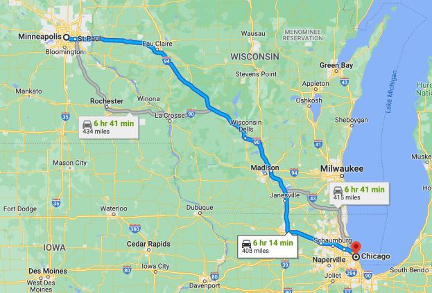
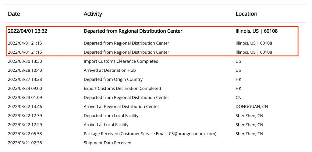
But I’m just sitting here waiting. It is a long wait for things to sit in such a status as shown above. I live roughly 7 hours from Chicago (the assumed hub for such distribution centers), and today is April 6th.
It arrived at that hub on March 28th and cleared customs on the 30th.
Getting a little (im)Patient 😉
I could have driven there last weekend, picked it up, had a nice weekend getaway with my wife………
In all seriousness though, I’m excited to get my hands on this and get it on the air, and I will be sure to post a review of my experience with it afterwards.
How will it compare to other kit radios I have? MCHF? QCX-mini (CW only, but the heritage is there)?
How will it compare to commercial QRP radios like the FT-817 or the MTR-4b?
Now to be patient…..
UPDATE
So after posting this, I sent a quick email to their support address asking if there was any update they could provide.
Exactly one hour later they posted an updated status – in Chinese – that says the same thing the previous status said.
Today, it is out for delivery.
Coincidence?
😀
Update Part 2
Received it and have already had it on the air. I am putting together all my findings and will update with a new post soon.
Yesterday I posted about my latest QCX mini kit from QRP Labs arriving. I had intended to wait until the weekend do dive into the build, but…
I couldn’t wait.
As I mentioned before, QRP Labs publishes incredibly well done documentation in their build instructions. You can see the latest version as of this writing here.
I ordered about a week prior, and it arrived via FedEx delivery in good shape and with everything well packed.
The kit is not necessarily difficult if you’ve built similar radios before, but I do recommend reading the manual through one time before starting. Everything is straight forward, but after a couple of hours of huffing solder fumes, it is easy to miss something and having read it first keeps things in mind along the way.
After taking stock of all the parts, I simply followed the manual step-by-step.
This is not a “how-to” post, rather a pic heavy of the steps I took when assembling.
First up is the *dreaded* T1 winding.
For 20 meters, it is 3×3 turns, with 1×30 turns
Actually T1 is really straightforward and simple to wind – if you read the instructions! The main point of the way they instruct you to wind it is so that all windings are the same direction. I think there are two in particular that have to match, but it is easiest to match all of them at the same time.
Soldered, checked, and ready for the next steps
With so many leads coming off of the toroid, taking it slow is needed. But again, follow the well laid out instructions and it comes together nicely.
Next up is the IC socket. Simple stuff, just make sure the notch is in the right place.
Capacitors are multiplying!Band Pass Filter windings starting to show upMain board is starting to get crowded
The Main Board comes together pretty quickly – there really isn’t a lot of parts to this kit that are not SMD and already on the board.
Next – moving on to the Display Board and Controls
The display is secured into place prior to soldering
NOTE: Do not toss the clipped leads from the components you’ve already soldered. You will need them for soldering the display leads. Take some of the clippings and use them as connections for the display to the PCB.
Soldering all the makeshift leads is – in my mind – the most tedious part of the build
I failed.
I didn’t remember to take any photos prior to the final smoke test shot below, but it is just mounting connectors and doing final connection checks prior to putting in some power and seeing if we let the “magic smoke” out or not.
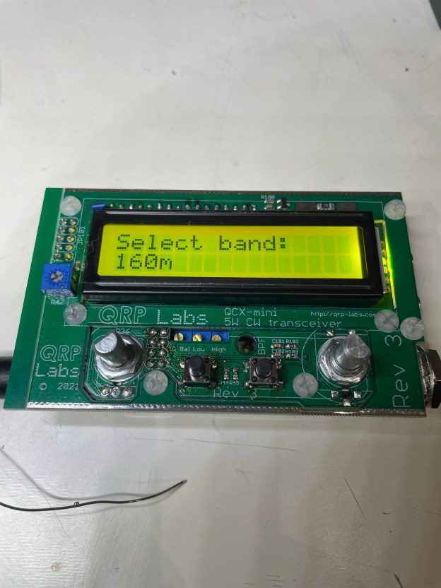
Success!!!
If all goes well, then upon first boot up you should see the above.
No magic smoke erupted, and it was time to get into calibration.
Calibration in progressThe whole QCX-mini “sandwich”. Very tight tolerances, but if you follow the manual it all fits the first time
Due to the tight tolerances of the kit and the optional case, I choose to line the case with electrical tape to avoid any potential of having any contacts cause any issues.
It is also recommended to take a moment to ensure that any soldered leads are closely trimmed prior to casing it up.
The kit in its new clothing – I highly recommend the optional case for this little radio as it is well made and fits like a glove
Conclusion
I cannot recommend this kit highly enough. They have created a well laid out kit, manual, and final product. The size of this thing is tiny – but having full-band CW coverage, with additional modes like WSPR puts it in a category all its own.
If they came out with a multi-band CW rig – even only 20/30/40 meters – they would absolutely kill the QRP POTA/SOTA market.
Even so, for the price and size, having 2-3 of these is not too much. This is my second purchase from them and I’m already contemplating a 3rd.