Category Archives: DIY

QCX Mini 20 Meter Build

Yesterday I posted about my latest QCX mini kit from QRP Labs arriving. I had intended to wait until the weekend do dive into the build, but…

I couldn’t wait.

As I mentioned before, QRP Labs publishes incredibly well done documentation in their build instructions. You can see the latest version as of this writing here.

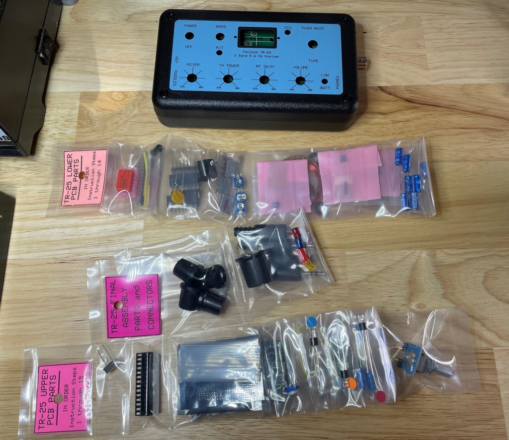
I ordered about a week prior, and it arrived via FedEx delivery in good shape and with everything well packed.

The kit is not necessarily difficult if you’ve built similar radios before, but I do recommend reading the manual through one time before starting. Everything is straight forward, but after a couple of hours of huffing solder fumes, it is easy to miss something and having read it first keeps things in mind along the way.

After taking stock of all the parts, I simply followed the manual step-by-step.

This is not a “how-to” post, rather a pic heavy of the steps I took when assembling.

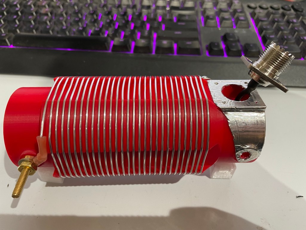
First up is the *dreaded* T1 winding.

For 20 meters, it is 3×3 turns, with 1×30 turns

Actually T1 is really straightforward and simple to wind – if you read the instructions! The main point of the way they instruct you to wind it is so that all windings are the same direction. I think there are two in particular that have to match, but it is easiest to match all of them at the same time.

Soldered, checked, and ready for the next steps

With so many leads coming off of the toroid, taking it slow is needed. But again, follow the well laid out instructions and it comes together nicely.

Next up is the IC socket. Simple stuff, just make sure the notch is in the right place.

Capacitors are multiplying!
Band Pass Filter windings starting to show up
Main board is starting to get crowded

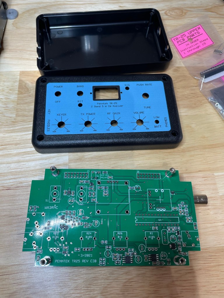
The Main Board comes together pretty quickly – there really isn’t a lot of parts to this kit that are not SMD and already on the board.

Next – moving on to the Display Board and Controls

The display is secured into place prior to soldering

NOTE: Do not toss the clipped leads from the components you’ve already soldered. You will need them for soldering the display leads. Take some of the clippings and use them as connections for the display to the PCB.

Soldering all the makeshift leads is – in my mind – the most tedious part of the build

I failed.

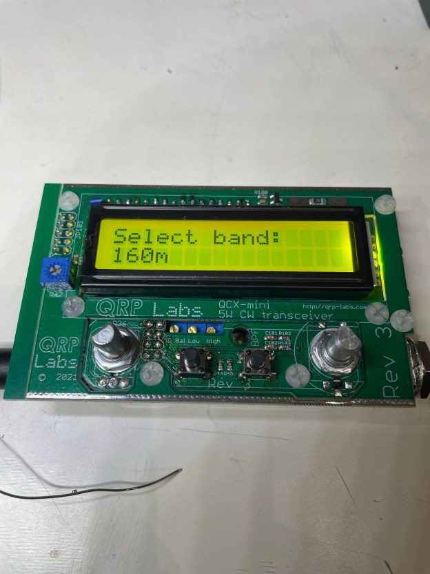
I didn’t remember to take any photos prior to the final smoke test shot below, but it is just mounting connectors and doing final connection checks prior to putting in some power and seeing if we let the “magic smoke” out or not.

Success!!!

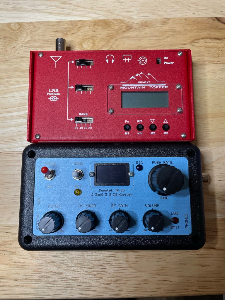
If all goes well, then upon first boot up you should see the above.

No magic smoke erupted, and it was time to get into calibration.

Calibration in progress
The whole QCX-mini “sandwich”. Very tight tolerances, but if you follow the manual it all fits the first time

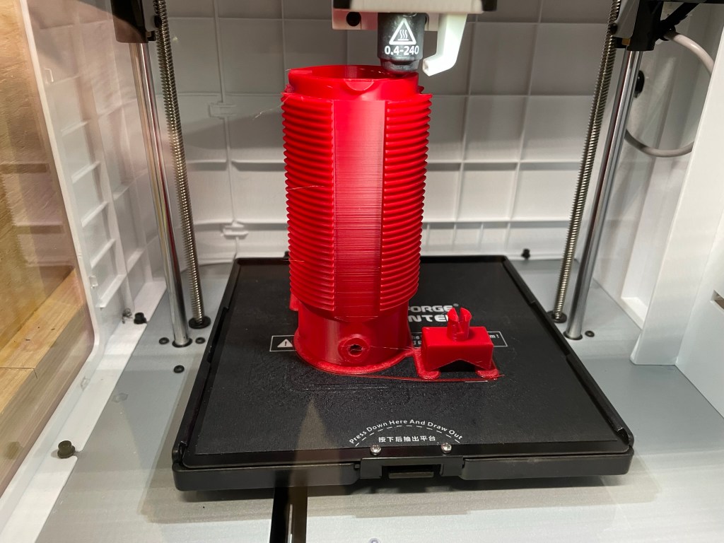
Due to the tight tolerances of the kit and the optional case, I choose to line the case with electrical tape to avoid any potential of having any contacts cause any issues.

It is also recommended to take a moment to ensure that any soldered leads are closely trimmed prior to casing it up.

The kit in its new clothing – I highly recommend the optional case for this little radio as it is well made and fits like a glove

Conclusion

I cannot recommend this kit highly enough. They have created a well laid out kit, manual, and final product. The size of this thing is tiny – but having full-band CW coverage, with additional modes like WSPR puts it in a category all its own.

If they came out with a multi-band CW rig – even only 20/30/40 meters – they would absolutely kill the QRP POTA/SOTA market.

Even so, for the price and size, having 2-3 of these is not too much. This is my second purchase from them and I’m already contemplating a 3rd.

Go get yours at https://qrp-labs.com/

Kit Build – Penntek TR-25 CW Radio

I first saw this kit online this last summer and was immediately intrigued. Fast forward to obtaining the December 2021 edition of QST where they did a review of the radio, and I knew I needed to get one.

The kit arrived in a well packed box about 1 week after placing my order. Unpacking it I have the following contents:

The PCBs are packed inside the radio case, and all the individual parts are packed together based on which part of the radio is being assembled.

For example, all the lower PCB parts are packed together and separate from the upper PCB parts. Even more convenient is that within each set of parts, each one is organized in the order of assembly. A welcome usability improvement over other kits I’ve done where parts arrive loose in a single plastic bag.

Also included are print outs of the assembly manuals, which are likewise separate pages for each section

Installation of all components is very straight forward. If you can solder, you can install all the parts.

There are 6 toroids that need winding. None are overly difficult (I still have flashbacks of T1 on the QCX mini ;)). The directions are very easy to follow and there are picture to validate your windings against.

I’m not going to go through a step-by-step of the assembly – the manuals do that for you. K0SSK also has a great post showing assembly and testing of the kit.

Assembled minus the bottom half of the case – need access to the pots to perform final checks and adjustments. Nice clear OLED screen. Always makes me smile to see things work as expected, even more so that I didn’t let the magic smoke out. 🙂

Quick Comparison

Looking at my other radios, the size lends itself to being compared with my Mountain Topper from LnR Precision.

Both come in at roughly the same dimensions. The Mountain Topper is 4 bands (80/40/30/20) compared to the TR-25’s 2 bands (20/40). While both radios offer QRP portability for commonly used bands, you can see that the tradeoff is either usability (a control for everything) vs breadth of capabilities (more bands, memory slots, etc.).

It is a little of an apple and orange comparison when putting a commercially built radio up against a kit given that the MTR comes assembled, but it is the only multi-band radio that is close to the TR-25 in my collection.

Minor Nits

There are a few things missing from this radio that others have, such as:

  • No memory slots for recorded SOTA/POTA/CQ messages
  • No visual indication of WPM for the Iambic-B (there is no Iambic-A support) keyer, the dial simply has Min/Max markers
  • The design is intuitive and having a dial/knob/toggle for all settings is actually nice thing given how many radios use menu and sub-menus to death, but they do stick up from the radio and might be subject to being broken in the field – time will tell

These are minor nits in my opinion as not everybody needs every bell and whistle to enjoy SOTA/POTA/QRP operations.

Conclusion

This post is focused on the quality of the kit and what I received for my money. I have not yet gotten in on the air and will follow up with my impressions there. For now, keeping things focused on the kit building side.

The TR-25 is easy to assemble, with 4-9 watts of output depending on band and power input, no hideous menu structures to memorize (everything has a switch or knob on the face). A great little radio that can be put together and be on the air quickly and easily.

Pick yours up for $199 USD at their online store.

NOTE: Penntek is coming out with the TR-45L 4 band transceiver that is currently in beta testing. It looks a bit “old school” and I’m definitely intrigued.

Building a 3D printed portable vertical antenna

I have a problem.

It is probably a common one amongst hams but it takes significant amount of time, effort, and resources in my spare time.

……

I like to create/build/home brew things. Like…all the time.

Its a sickness (or so my wife thinks).

Anyway.

I have had a QRP Guys Portable Tri-band Vertical kit for a while, and it is a great kit that is easy to assemble and works great. It is small, lightweight, and provides 20/30/40 meter coverage. Run the radiating element up a collapsible pole and you’ve got a field antenna that sets up quickly.

Since I was raised an “Army Brat” and it was drilled into me from an early age that “two is one, one is none”, I never stop at having just one POTA/SOTA vertical antenna system.

My Super Antenna, CHA MPAS Lite, Buddistick, Wolf River Coils Silver Bullet, and others can attest to that.

I might have another problem – antenna addition!

After having spent some time researching options, I decided on the following factors being important to me:

  • No kit – I’ve done multiple kits and while I enjoy them and will still do more in the future, I wanted to build something more “DIY” than that
  • Lightweight
  • Multi-band (Ideally 20/30/40/60/80)
  • Most parts (if not all) are already in my possession amongst my surplus of wires, connectors, and such
  • Inexpensive in case I do have to buy anything (i.e. less than $10 USD) out of pocket (not including what I have already purchased for past projects)
  • Occupy some degree of free time 😉

I then settled on wanting a tapped coil design that would allow me to play with the tuning to find the sweet spots per band, and after looking at various home brewed ideas, I found SA2CLC‘s Vertical Antenna Loading Coil on Thingiverse.

Printing the Parts

It checked all of the boxes above and, after downloading the STL files, I begun printing the coil form and mounts. I have a couple of printers, but find that my Flashforge Adventurer 3 provides the most consistent ABS prints for me. I’m not a fan of the constrained print area of this printer, but it does do a good job at whatever I throw at it.

The photo above is about 90% complete. I have to give SA2CLC a lot of credit for an elegant design. No supports are needed to print this model, and it is well laid out and logical. Great work!

I chose to use ABS and printed the parts at 50% infill at standard quality. My goal here was to have a balance between weight and strength, with ABS widely used in products where durability matters.

About 15 hours later I had three parts; the coil form itself, and two mounts which allow you to affix the coil to a telescopic pole.

Upon completion of the print, I immediately realized a mistake on my part – I chose ABS for all of the parts, and the two mounts require some flex in the prongs so that they can be inserted into the body of the coil.

ABS doesn’t like to flex like some other plastics do, and I quickly snapped one prong off of the first piece I tried to insert into the coil, so I kicked off another print of just the mounts using PETG. That is what SA2CLC used and posted to his model page on Thingiverse.

That is another problem I have – reading the directions!

I then sent off a print to my Creality Ender 3 (I don’t have the higher temp nozzle to allow for PETG prints on the Flashforge – yet) and within a couple of hours had two new mounts that won’t break on me.

Assembling the Coil

In addition to the ABS/PETG printed parts, I used the following materials:

  • 1.25″ non-insulated alligator clips
  • SO239 chassis mount connectors
  • 18 gauge aluminum wire
  • 6-32 machine screws and nuts
  • 4mm binding post connectors
  • short length of 18 gauge wire to connect the center plug of the SO239 to the coil
  • ring terminals
  • aluminum tape (see below)

I followed the excellent YouTube video that the creator posted as a part of his model. The two places that I deviated slightly was first in connecting the ground for the SO239 to the binding post connectors. Why? I had seen this used in other projects online and had been wanting to apply it to a project of mine for a while, so I went ahead and added it here. Time will tell if this is effective or not, or even if it will stay put or not.

UPDATE: I found some thin sheet metal from some ducting work I had done previously that I decided would be more durable than the aluminum tape shown in the next photo. I cut out a piece that is roughly the same dimensions as what is shown below. As before, we’ll see how effective this is over time.

You can see the white PETG mounts on the bottom of the coil – one left and one right.

The second deviation was the use of another 6-32 machine screw and wingnut for the radiating element connection instead of a binding post as in the creator’s design. As with the aluminum tape, I may change that out but I’ve used wingnuts on multiple antennas and find them to be solid connections that are still quick to add/remove wires to. That is especially true when the wires use spade connections.

We’ll see how it goes in the field.

Stay tuned for Part 2 – Assembly and Initial Testing